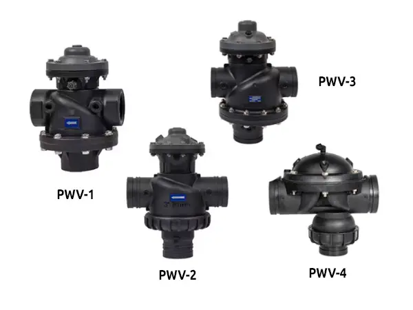
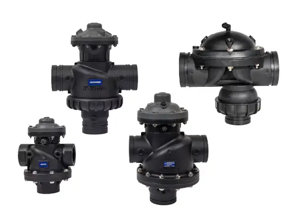
Two-position three-way valve models

Two-position three-way valve is a hydraulically driven diaphragm control valve with low-pressure sealing and smooth flow direction switching. It can be combined with sand filter or disc filter / screen filter to form an automatic backwash filtration system. It can also be used in water supply systems to change the flow direction of water.

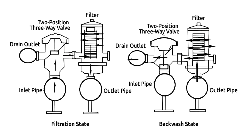
The water to be treated enters the two-position three-way valve through the inlet pipe, and under valve control, the water flow enters each unit for filtration.
The filtered water flows from the internal channel of the filtration unit into the outlet. As filtration progresses, the impurities adsorbed by the filter increase. When the pressure difference reaches the set value or the set time, the system enters the backwash mode. The controller first sends a signal to the three-way valve corresponding to the first filter unit, which will change the direction of the water flow, close the inlet, and open the drain outlet. Under pressure, the backwash water flows through the outlet pipe into the filter for washing, and the sewage is discharged from the drain outlet.
After washing, the unit returns to the filtration mode, and the system performs backwash on the next unit until all units are washed and the system returns to the filtration mode.
Two-position three-way valve models
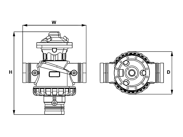
PWV-1, PWV-2 & PWV-3 model dimension diagrams
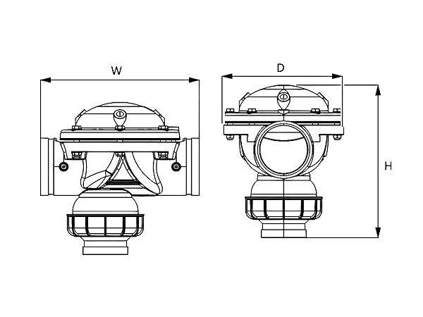
PWV-4 Model Dimension Diagram
| Product Model | D (mm) |
W (mm) |
H (mm) |
|---|---|---|---|
| PWV-1 | 274 | 180 | 160 |
| PWV-2 | 378 | 287 | 192 |
| PWV-3 | 464 | 277 | 260 |
| PWV-4 | 316 | 187 | 170 |
| Product Model | Specifications | Connection Method | Maximum Flow Rate (m3/h) |
Working Pressure (bar) |
Weight (kg) |
|---|---|---|---|---|---|
| PWV-1 | 2" x 2" x 2" | BSP / NPT / VIC | 30 | 0.7–10 | 2.8 |
| PWV-2 | 3" x 3" x 3" | VIC | 50 | 0.7–10 | 5.5 |
| PWV-3 | 4" x 4" x 4" (3") | VIC | 100 | 0.7–10 | 9.9 |
| PWV-4 | 4" x 4" x 3" (4") | VIC | 80 | 0.7–10 | 5.5 |