
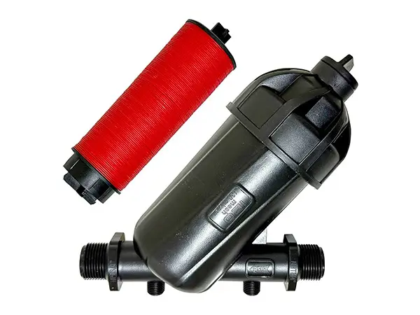
In modern agricultural irrigation, water quality management is crucial. The disc filter, as an efficient and reliable water filtration device, utilizes its unique multi-layer disc design to effectively remove suspended solids and particulates from water, ensuring the smooth operation of the irrigation system.
Its automatic backwash function not only reduces maintenance costs but also enhances the operational efficiency of the system. In irrigation systems, disc filters are commonly used in conjunction with primary filters as secondary filters. Whether in drip or sprinkler systems, disc filters provide stable filtration performance, making them an ideal choice for agricultural irrigation.

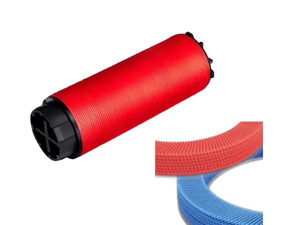
The disc filter element is composed of a set of discs with grooves on both sides. The intersection points formed by the groove edges can trap solid particles in the water. Due to the simultaneous surface interception and depth coagulation effects, the filtration efficiency is greatly improved.
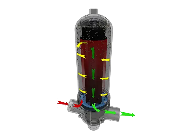
Water enters the filter through the inlet. As it passes through the filter discs, the discs are tightly pressed together under the force of the spring and hydraulic pressure. Impurity particles are trapped at the intersection points of the discs, and the filtered water flows out through the main channel of the filter.
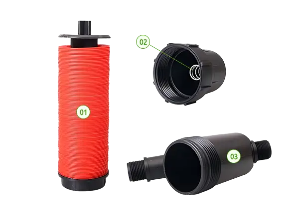
Disc filters can be manually or automatically washed. For manual washing, the filter element can be removed, and the compression nut loosened, then rinsed with water.
For automatic washing, when a certain pressure difference or time is reached, the system automatically enters the backwash state. The controller adjusts the valve to change the water flow direction, and the backwash pressure tightens the spring, loosening the discs. The nozzles on the filter element's support column spray tangentially, causing the discs to rotate and wash away impurities trapped on the discs. When the backwash is completed, the flow direction changes again, the discs are pressed tightly once more, and the system re-enters the filtration state.

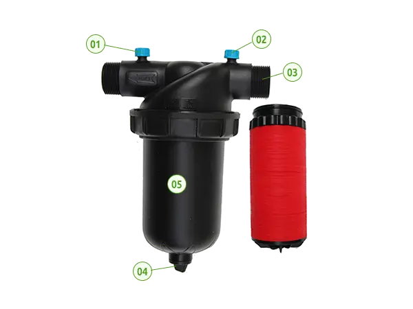
Y-type Disc Filter

T-type Disc Filter

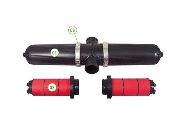
H-type Disc Filter
The Y-type Disc Filter is mainly composed of a housing and a disc filter element, providing micron-level in-depth filtration with high filtration efficiency and large contaminant capacity.
The Y-shaped design is suitable for confined spaces, and the filter element is easy to disassemble, making cleaning and maintenance simple.
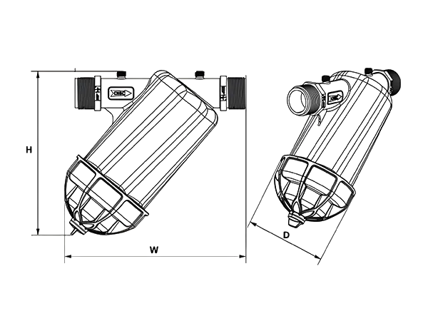
| Model | H (mm) |
W (mm) |
D (mm) |
|---|---|---|---|
| YD-1 | 173 | 176 | 93 |
| YD-2 | 173 | 192 | 83 |
| YD-3 | 173 | 176 | 93 |
| YD-4 | 173 | 192 | 83 |
| YD-5 | 230 | 250 | 120 |
| YD-6 | 230 | 250 | 120 |
| YD-7 | 260 | 290 | 140 |
| YD-8 | 330 | 360 | 168 |
| YD-9 | 330 | 360 | 168 |
| Model | Connection Pipe Diameter (BSP/NPT) |
Filter Rating (Mesh) |
Maximum Flow Rate (m3/h) |
Working Pressure (bar) |
Filtration Area (cm2) |
Weight (kg) |
|---|---|---|---|---|---|---|
| YD-1 | 3/4" | 120 | 5 | 8 | 180 | 0.39 |
| YD-2 | 3/4" | 120 | 5 | 8 | 195 | 0.35 |
| YD-3 | 1" | 120 | 6 | 8 | 180 | 0.39 |
| YD-4 | 1" | 120 | 6 | 8 | 195 | 0.35 |
| YD-5 | 1-1/4" | 40 / 80 / 120 / 150 | 10 | 8 | 300 | 0.96 |
| YD-6 | 1-1/2" | 40 / 80 / 120 / 150 | 14 | 8 | 300 | 0.96 |
| YD-7 | 2" | 40 / 80 / 120 / 150 | 25 | 8 | 525 | 1.36 |
| YD-8 | 2-1/2" | 80/120 | 30 | 8 | 600 | 2.60 |
| YD-9 | 3" | 80/120 | 35 | 8 | 600 | 2.70 |
The T-type disc filter mainly consists of a filter element, a housing, and atop cover. Its inlet and outlet are usually located on the same side, forming a 'T' shape. This design is suitable for confined spaces.
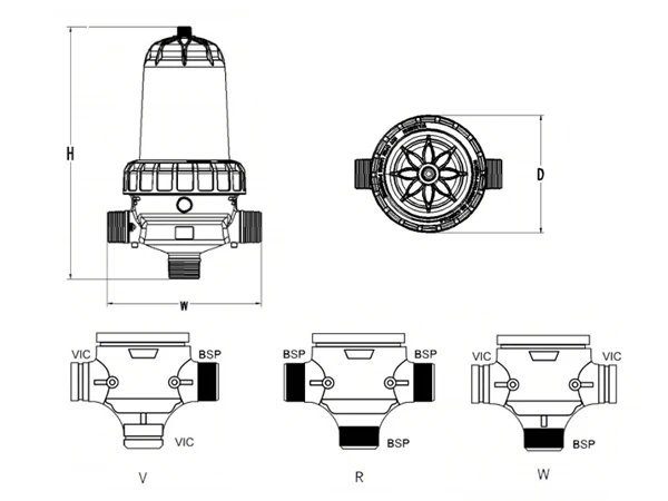
| Model | H (mm) |
X (mm) |
D (mm) |
|---|---|---|---|
| TD-1 | 280 | 205 | 139 |
| TD-2 | 280 | 205 | 139 |
| TD-3 | 280 | 205 | 139 |
| TD-4 | 620 | 320 | 220 |
| TD-5 | 740 | 320 | 220 |
| TD-6 | 630 | 320 | 220 |
| TD-7 | 750 | 320 | 220 |
| TD-8 | 630 | 340 | 220 |
| TD-9 | 750 | 340 | 220 |
| TD-10 | 480 | 292 | 233 |
| TD-11 | 630 | 292 | 233 |
| TD-12 | 528 | 355 | 233 |
| TD-13 | 678 | 355 | 233 |
| Model | Connection Pipe Diameter (BSP/NPT) |
Filter Rating (Mesh) |
Maximum Flow Rate (m3/h) |
Working Pressure (bar) |
Filtration Area (cm²) |
Weight (kg) |
|---|---|---|---|---|---|---|
| TD-1 | 1-1/4" | 40 / 80 / 120 / 150 | 10 | 8 | 300 | 1.01 |
| TD-2 | 1-1/2" | 40 / 80 / 120 / 150 | 14 | 8 | 300 | 1.01 |
| TD-3 | 2" | 40 / 80 / 120 / 150 | 20 | 8 | 300 | 1.03 |
| TD-4 | 2" | 40 / 80 / 120 / 150 / 200 / 300 | 30 | 10 | 1200 | 6.2 |
| TD-5 | 2" | 40 / 80 / 120 / 150 / 200 / 300 | 30 | 10 | 1700 | 7.2 |
| TD-6 | 2-1/2" | 40 / 80 / 120 / 150 / 200 / 300 | 40 | 10 | 1200 | 6.4 |
| TD-7 | 2-1/2" | 40 / 80 / 120 / 150 / 200 / 300 | 40 | 10 | 1700 | 7.3 |
| TD-8 | 3" | 40 / 80 / 120 / 150 / 200 / 300 | 50 | 10 | 1200 | 6.5 |
| TD-9 | 3" | 40 / 80 / 120 / 150 / 200 / 300 | 50 | 10 | 1700 | 7.4 |
| TD-10 | 2" | 40 / 80 / 120 / 150 / 200 / 300 | 30 | 10 | 1050 | 4.2 |
| TD-11 | 2" | 40 / 80 / 120 / 150 / 200 / 300 | 30 | 10 | 1660 | 5.4 |
| TD-12 | 3" | 40 / 80 / 120 / 150 / 200 / 300 | 50 | 10 | 1050 | 4.6 |
| TD-13 | 3" | 40 / 80 / 120 / 150 / 200 / 300 | 50 | 10 | 1660 | 5.9 |
The main structure of the H-type disc filter is H-shaped, primarily composed of 2 disc filter elements and a plastic housing. Its inlet and outlet are usually located on both sides, forming an 'H' shape. This design facilitates the observation and cleaning of the filter.
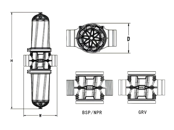
| Model | H (mm) |
W (mm) |
D (mm) |
|---|---|---|---|
| HD-1 | 940 | 335 | 220 |
| HD-2 | 1200 | 335 | 220 |
| HD-3 | 960 | 340 | 220 |
| HD-4 | 1220 | 340 | 220 |
| Model | Connection Pipe Diameter (BSP/NPT/GRV) |
Filter Rating (Mesh) |
Maximum Flow Rate (m3/h) |
Maximum Pressure (bar) |
Filtration Area (cm²) |
Weight (kg) |
|---|---|---|---|---|---|---|
| HD-1 | 3" | 40 / 80 / 120 / 150 / 200 / 300 | 50 | 10 | 2400 | 10.9 |
| HD-2 | 3" | 40 / 80 / 120 / 150 / 200 / 300 | 60 | 10 | 3400 | 13.1 |
| HD-3 | 4" | 40 / 80 / 120 / 150 / 200 / 300 | 70 | 10 | 2400 | 11.3 |
| HD-4 | 4" | 40 / 80 / 120 / 150 / 200 / 300 | 100 | 10 | 3400 | 13.5 |