
Sand filters are commonly used as primary filters, utilizing quartz sand as the filter medium. Under certain pressure, water with higher turbidity is passed through a certain thickness of granular or non-granular quartz sand, effectively trapping and removing suspended solids, organic matter, colloidal particles, microorganisms, chlorine, and some heavy metal ions from the water. This results in reduced water turbidity and improved water quality, making it a highly efficient filtration device.


The structure of a sand filter is simple and efficient, mainly consisting of the following parts:


When the system is in the filtration state, pressurized water flows from the filter tank inlet into the water distribution system, reaching the sand filter layer evenly. As the water flows through the sand filter layer, suspended solids are trapped by the filter media. At the bottom of the filter, there is a water collector with slits, which evenly collects the filtered clean water and allows it to flow out of the filter.
As impurities continuously accumulate in the sand filter layer, the pressure loss increases. When the pressure differential reaches a certain set value or the set cleaning time is reached, the system will automatically switch to the backwash state. Pressurized water enters the sand filter layer through the water collector, scouring it to dislodge the trapped contaminants and discharge them from the filtration system. After backwashing for at least 2 minutes, the valve automatically switches the system to the filtration state.
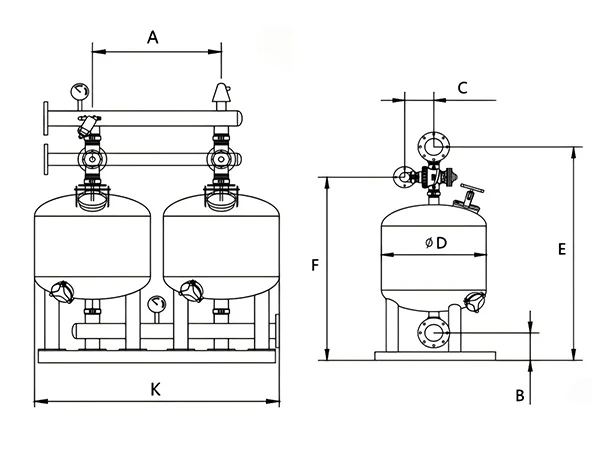
| Model | Size (mm) | ||||||
|---|---|---|---|---|---|---|---|
| D | A | B | C | E | F | K | |
| SF1-2 | 600 | 700 | 130 | 240 | 1450 | 1215 | 1330 |
| SF2-2 | 700 | 800 | 140 | 240 | 1580 | 1305 | 1520 |
| SF2-3 | 700 | 800 | 140 | 300 | 1580 | 1305 | 2320 |
| SF3-2 | 800 | 900 | 140 | 300 | 1620 | 1345 | 1720 |
| SF3-3 | 800 | 900 | 170 | 300 | 1695 | 1395 | 2620 |
| SF4-2 | 900 | 1000 | 140 | 300 | 1660 | 1385 | 1920 |
| SF4-3 | 900 | 1000 | 170 | 300 | 1740 | 1440 | 2920 |
| SF5-2 | 1000 | 1150 | 170 | 300 | 1785 | 1490 | 2120 |
| SF5-3 | 1000 | 1150 | 200 | 300 | 1900 | 1550 | 3220 |
| SF6-2 | 1200 | 1400 | 170 | 300 | 1925 | 1593 | 2620 |
| SF6-3 | 1200 | 1400 | 200 | 380 | 2005 | 1648 | 4020 |
| SF6-4 | 1200 | 1400 | 200 | 380 | 2025 | 1750 | 5420 |
| Model | Sand Tank Diameter (mm) |
Number of Sand Tanks | Maximum Pressure (bar) |
Filtration Area (m2) |
Backwash Flow Rate (m³/h) |
Flow Rate Range (m³/h) |
|---|---|---|---|---|---|---|
| SF1-2 | 600 | 2 | 10 | 0.6 | 15 | 30–50 |
| SF2-2 | 700 | 2 | 10 | 0.8 | 20 | 50–70 |
| SF2-3 | 700 | 3 | 10 | 1.2 | 20 | 70–90 |
| SF3-2 | 800 | 2 | 10 | 1.0 | 25 | 60–80 |
| SF3-3 | 800 | 3 | 10 | 1.5 | 25 | 90–130 |
| SF4-2 | 900 | 2 | 10 | 1.2 | 35 | 90–100 |
| SF4-3 | 900 | 3 | 10 | 1.8 | 35 | 120–150 |
| SF5-2 | 1000 | 2 | 10 | 1.6 | 40 | 90–100 |
| SF5-3 | 1000 | 3 | 10 | 2.4 | 40 | 130–150 |
| SF6-2 | 1200 | 2 | 10 | 2.2 | 50 | 140–180 |
| SF6-3 | 1200 | 3 | 10 | 3.3 | 50 | 150–250 |
| SF6-4 | 1200 | 4 | 10 | 4.4 | 50 | 200–350 |