
Pressure reducing valve is a device that controls water flow pressure, primarily used to reduce high water pressure to a safe level suitable for irrigation systems. By regulating and stabilizing water pressure, it ensures the efficiency of the irrigation system and the healthy growth of crops.
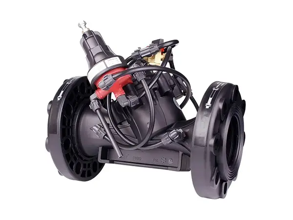


Manual Pressure Reducing Valve

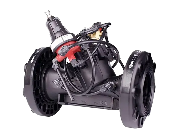
Electromagnetic Pressure Reducing Valve
Manual pressure reducing valve is a hydraulically driven diaphragm type hydraulic control valve that reduces water flow pressure by manually adjusting the valve opening. Users can set a target pressure as needed and manually adjust the valve to ensure that the downstream pipeline maintains a relatively constant pressure, protecting the irrigation system and plants from improper pressure damage.
It is widely used in pressure reducing stations, systems with significant water supply pressure variations, energy-saving irrigation systems, and terrains with large irrigation drops, to reduce the pressure of low-lying systems, decrease the pressure in field pipelines, and maintain a certain pressure value.
In the diagram, 1 is the pilot valve, 2 is the drain outlet, 3 is the control chamber, and 4 is the diaphragm.
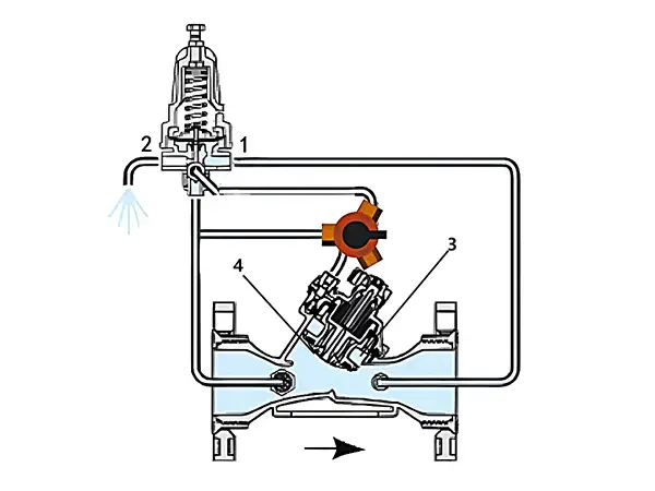
When the downstream pressure is below the required set point, the pilot valve opens the drain outlet, discharging water from the control chamber to the atmosphere, reducing the pressure in the control chamber, causing the diaphragm to move upward, and opening the valve.
When the downstream pressure is above the required set point, the pilot valve closes the drain outlet, allowing water to flow from upstream to the control chamber, increasing the pressure in the control chamber, causing the valve to tend to close. Alternatively, use the manual switch valve to adjust to close.
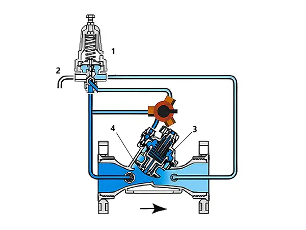
When the sensed pressure matches the set value, the pilot valve blocks both the drain outlet and the inlet, thus locking the pressure in the control chamber. The valve maintains the final opening degree until the pilot valve senses a change in system pressure again.
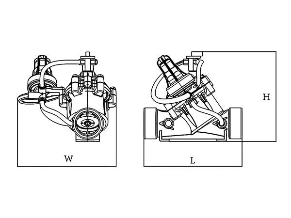
| Product Model | L (mm) |
W (mm) |
H (mm) |
|---|---|---|---|
| PRV-1 | 226 | 120 | 192 |
| PRV-2 | 230 | 150 | 230 |
| PRV-3 | 320 | 160 | 280 |
| PRV-4 | 350 | 170 | 330 |
| PRV-5 | 436 | 240 | 430 |
| Product Model | Specifications | Connection Method | Maximum flow rate (m3/h) |
Working Pressure (bar) |
Weight (kg) |
|---|---|---|---|---|---|
| PRV-1 | 1.5" x 1.5" | BSP / NPT | 18 | 0.35–10 | 1.86 |
| PRV-2 | 2" x 2" | BSP / NPT / VIC | 30 | 0.35–10 | 2.16 |
| PRV-3 | 3" x 3" | BSP / NPT / Flange / VIC | 50 | 0.35–10 | 2.04 (Flanged 3.42) |
| PRV-4 | 4" x 4" | Flange | 100 | 0.35–10 | 6 |
| PRV-5 | 6" x 6" | Flange | 150 | 0.35–10 | 12 |
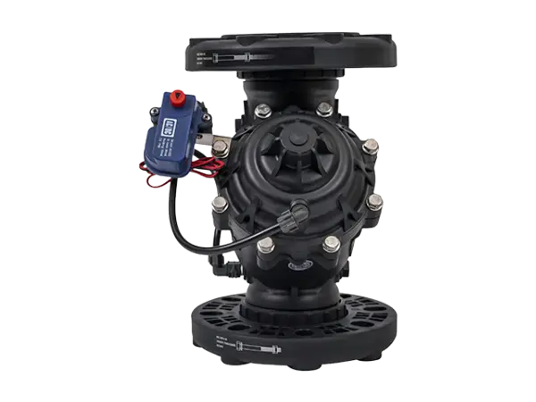
The electromagnetic pressure reducing valve is a hydraulically driven diaphragm type hydraulic control valve with an electromagnetic valve control device. Regardless of flow fluctuations, the valve can reduce the high pressure before the valve to a low pressure after the valve and maintain stability. When the pressure decreases, the valve fully opens and can be controlled to open or close via electrical signals.
It is widely used in computer-controlled irrigation systems, pressure reducing stations, systems with significant water supply pressure variations, energy-saving irrigation systems, distant or higher terrain plots, and water distribution networks.
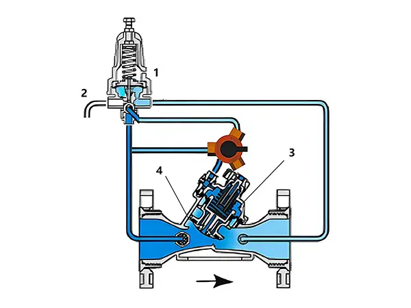
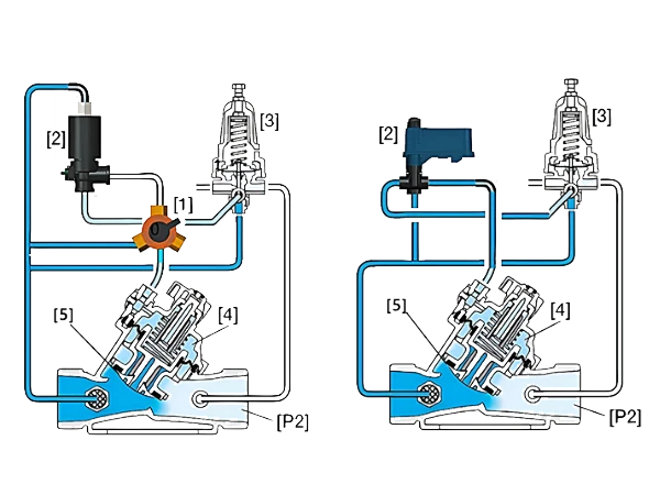
In the diagram, [1] is a three-way switch, [2] is a solenoid head, [3] is a pressure reducing pilot valve, [4] is the control chamber, [5] is the diaphragm, and [P2] is the downstream pressure.
The three-way switch connects the solenoid head or the pressure reducing pilot valve to the valve control chamber.
When the solenoid valve is closed, the pressure reducing pilot valve opens when the downstream pressure rises above the pilot valve's set value, allowing pressure to enter the control chamber. The diaphragm moves under pressure, causing the valve to close slowly; similarly, when the downstream pressure is below the pilot valve's set value, it causes the valve to fully open.
When the solenoid valve is open, it switches through electrical signal control, guiding the pipeline pressure into the control chamber. The increased pressure in the control chamber causes the valve to close. The solenoid valve can also be operated manually.
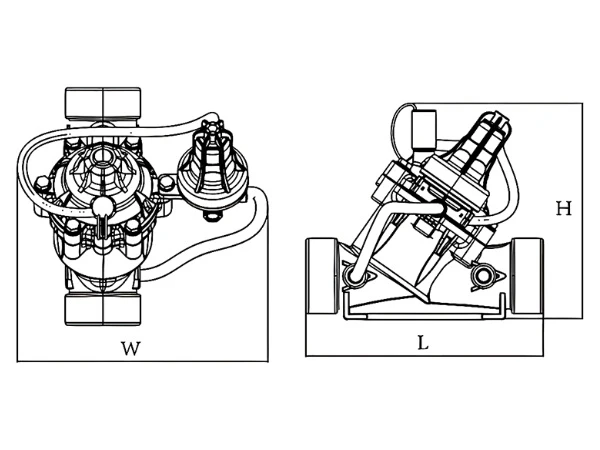
| Product Model | L (mm) |
W (mm) |
H (mm) |
|---|---|---|---|
| SPR-1 | 226 | 120 | 192 |
| SPR-2 | 230 | 150 | 230 |
| SPR-3 | 320 | 160 | 280 |
| SPR-4 | 350 | 170 | 330 |
| SPR-5 | 436 | 240 | 430 |
| Product Model | Specifications | Connection Method | Solenoid Voltage (V) |
Maximum Flow Rate (m3/h) |
Working Pressure (bar) |
Weight (kg) |
|---|---|---|---|---|---|---|
| SPR-1 | 1.5" x 1.5" | BSP / NPT | DC24V / AC24V / DC12V (Pulse) | 15 | 0.35–10 | 1.9 |
| SPR-2 | 2" x 2" | BSP / NPT / VIC | DC24V / AC24V / DC12V (Pulse) | 25 | 0.35–10 | 2.2 |
| SPR-3 | 3" x 3" | BSP / NPT / Flange / VIC | DC24V / AC24V / DC12V (Pulse) | 50 | 0.35–10 | 2.04 (flanged 3.42) |
| SPR-4 | 4" x 4" | Flange | DC24V / AC24V / DC12V (Pulse) | 100 | 0.35–10 | 6 |
| SPR-5 | 6" x 6" | Flange | DC24V / AC24V / DC12V (Pulse) | 150 | 0.35–10 | 12.1 |