
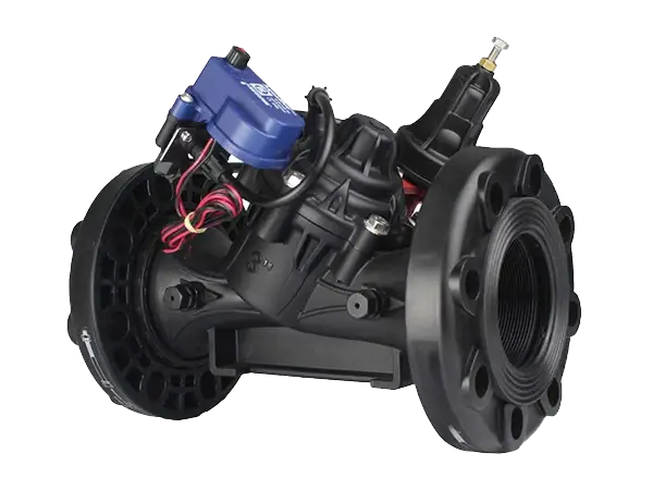
Pressure holding valve is a type of pressure regulating device used in pipeline systems, which automatically adjusts the valve opening based on changes in fluid pressure. This regulation typically relies on springs and diaphragms within the valve, which are sensitive to pressure changes and can precisely control the valve's response.
It can maintain a specific pressure within the system to prevent efficiency decrease or equipment damage caused by excessively low or high pressure, ensuring stable system operation.


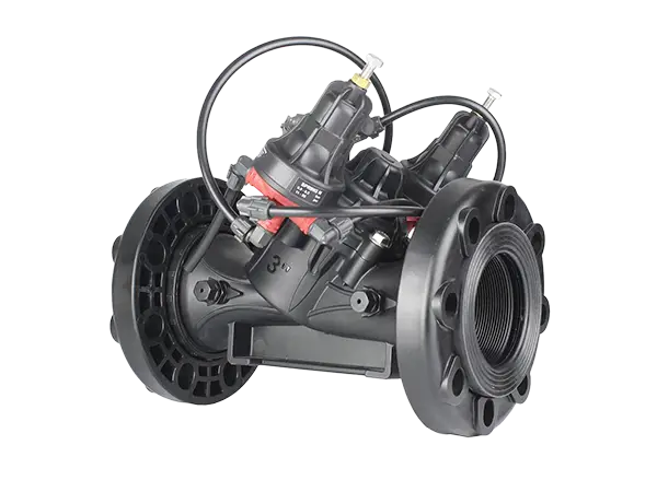
Manual Pressure Holding Valve

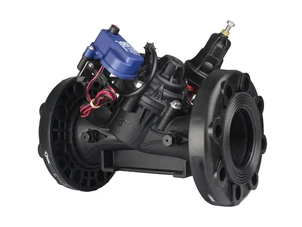
Electromagnetic Pressure Holding Valve
The manual pressure holding valve is a hydraulically operated diaphragm-type hydraulic control valve that can maintain a preset minimum upstream pressure. When the pressure within the pipeline system is too low or too high, it will automatically open or close, thereby maintaining the stability of the water flow and protecting the system equipment.
It is widely used in pipeline water injection control schemes, preventing pipeline emptying, systems with significant supply pressure variations, and energy-saving irrigation systems.
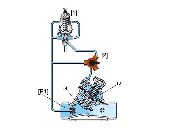
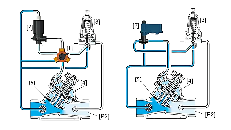
In the diagram, [1] is a pressure holding pilot valve, [2] is a three-way switch, [3] is the control chamber, [4] is the diaphragm, and [P1] is the upstream pressure.
Valve closing: When the upstream pressure is lower than the preset pressure value, the pressure holding pilot valve opens, water flows into the control chamber, the water pressure in the control chamber increases, the diaphragm moves downward, and the valve closes slowly.
Valve opening: When the upstream pressure rises above the set value, the pressure holding pilot valve closes, water flows out of the control chamber, the water pressure in the control chamber decreases, the diaphragm moves upward, and the valve opens slowly.
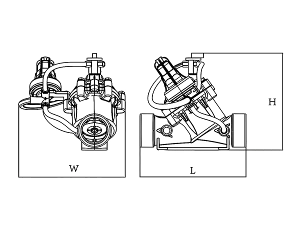
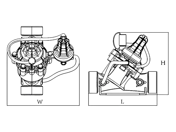
| Product Model | L (mm) |
W (mm) |
H (mm) |
|---|---|---|---|
| PHV-1 | 226 | 120 | 192 |
| PHV-2 | 230 | 150 | 230 |
| PHV-3 | 320 | 160 | 280 |
| PHV-4 | 350 | 170 | 330 |
| PHV-5 | 436 | 240 | 430 |
| Product Model | Specifications | Connection Method | Maximum Flow Rate (m3/h) |
Operating Pressure (bar) |
Weight (kg) |
|---|---|---|---|---|---|
| PHV-1 | 1.5" x 1.5" | BSP / NPT | 18 | 0.35–10 | 1.86 |
| PHV-2 | 2" x 2" | BSP / NPT / VIC | 30 | 0.35–10 | 2.16 |
| PHV-3 | 3" x 3" | BSP / NPT / Flange / VIC | 50 | 0.35–10 | 2.04 (3.42 with flange) |
| PHV-4 | 4" x 4" | Flange | 100 | 0.35–10 | 6 |
| PHV-5 | 6" x 6" | Flange | 150 | 0.35–10 | 12 |
The electromagnetic pressure holding valve can maintain a pre-set minimum upstream pressure, and the valve fully opens when the system pressure exceeds the set value. The valve can be controlled to open or close via an electrical signal.
It is widely used in computer-controlled irrigation systems, pipeline water injection control schemes, prevention of pipeline drainage, distant or higher terrain plots, maintaining backwash pressure of field irrigation system filters, and energy-saving irrigation systems.
In the figure, [1] is a three-way switch, [2] is the solenoid head, [3] is the pressure reducing pilot valve, [4] is the control chamber, [5] is the diaphragm, and [P2] is the downstream pressure
The three-way switch connects the solenoid or pressure holding pilot valve to the valve control chamber.
When the solenoid valve is closed, if the pressure behind the pressure holding pilot valve is lower than the set value, pressure enters the control chamber, causing the diaphragm to move under pressure, allowing the valve to close slowly; similarly, if the pressure rises above the set value, the valve fully opens.
When the solenoid valve is open, it switches under the control of an electrical signal, guiding pipeline pressure into the control chamber through the solenoid head, increasing the control chamber pressure to prompt the valve to close.
| Product Model | L (mm) |
W (mm) |
H (mm) |
|---|---|---|---|
| SPH-1 | 226 | 120 | 192 |
| SPH-2 | 230 | 150 | 230 |
| SPH-3 | 320 | 160 | 280 |
| SPH-4 | 350 | 170 | 330 |
| SPH-5 | 436 | 240 | 430 |
| Product Model | Specifications | Connection Method | Solenoid Voltage (V) |
Maximum Flow Rate (m3/h) |
Operating Pressure (bar) |
Weight (kg) |
|---|---|---|---|---|---|---|
| SPH-1 | 1.5" x 1.5" | BSP / NPT | DC24V / AC24V / DC12V (Pulse 0) | 15 | 0.35–10 | 1.9 |
| SPH-2 | 2" x 2" | BSP / NPT / VIC | DC24V / AC24V / DC12V (Pulse 0) | 25 | 0.35–10 | 2.2 |
| SPH-3 | 3" x 3" | BSP / NPT / Flange / VIC | DC24V / AC24V / DC12V (Pulse 0) | 50 | 0.35–10 | 2.04 (3.42 with flange) |
| SPH-4 | 4" x 4" | Flange | DC24V / AC24V / DC12V (Pulse 0) | 100 | 0.35–10 | 6 |
| SPH-5 | 6" x 6" | Flange | DC24V / AC24V / DC12V (Pulse 0) | 150 | 0.35–10 | 12.1 |