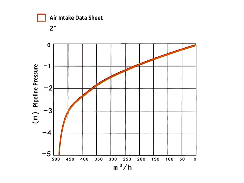
2" air intake data sheet

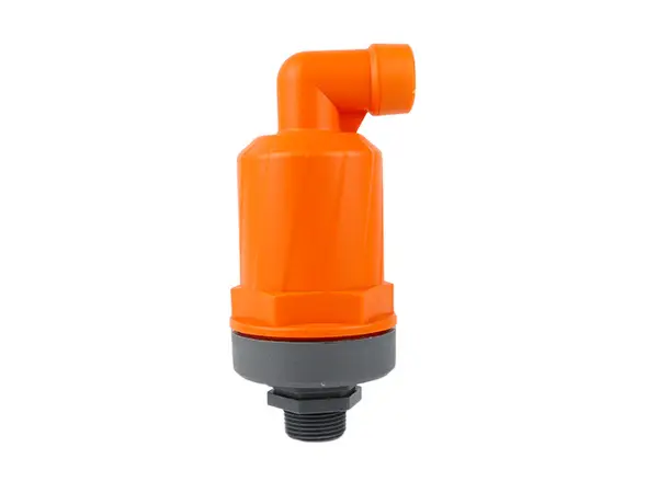
Kinetic air vent and vacuum relief valves are used to release or intake air during system start-up and shutdown, preventing pipeline damage due to abnormal pressure, such as pipe rupture or deformation.
When the irrigation system starts, the kinetic air vent and vacuum relief valve expels air from the pipeline, reducing water flow resistance, ensuring smooth water flow, and improving the uniformity and efficiency of irrigation. When the system is shut down or there is a sudden pressure drop, the valve will intake air to prevent the pipeline from being damaged by a vacuum effect.
It is commonly used in irrigation systems with long pipelines and significant elevation changes, especially at high points or on slopes, to prevent airlock formation.

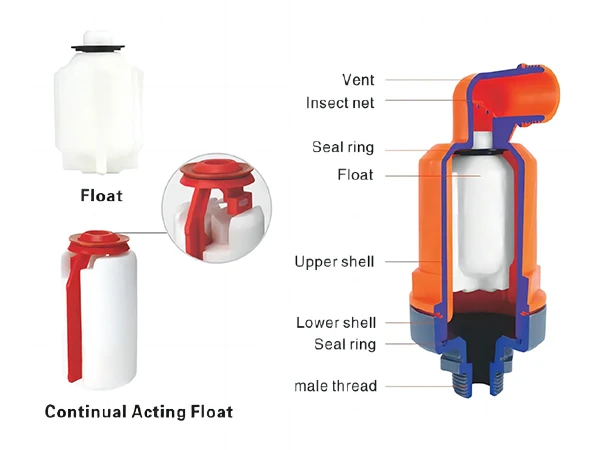
The working principle of the kinetic air vent and vacuum relief valve is to automatically control the air intake and exhaust in the irrigation system to protect the pipeline system from damage and ensure continuous and stable water flow.
Air intake: When the irrigation system starts, water begins to fill the empty pipeline. At this time, the pressure inside the pipeline will drop rapidly. To prevent the pipeline from collapsing due to excessive negative pressure, the kinetic air vent and vacuum relief valve will automatically open, allowing external air to enter the pipeline, thereby balancing the internal and external pressure.
Air exhaust: During the process of filling the irrigation system with water, the air originally in the pipeline is gradually pushed to the high points or moved to the outlets of the pipeline by the flow of water. Kinetic air vent and vacuum relief valves are installed at the high points of the system and can automatically open to release the air, preventing air accumulation from forming air pockets that affect the efficiency and uniformity of water flow. In addition, releasing air also helps prevent the phenomenon of water hammer, which refers to the severe pressure fluctuations within the system that can occur when water flow suddenly stops or changes direction, potentially causing damage to the pipeline.
| Product Model | Specifications | Connection Method | Exhaust Area (mm2) |
Operating Pressure (bar) |
Dimensions (mm) |
Weight (kg) |
|---|---|---|---|---|---|---|
| C-10 | 1" | BSP / NPT | 454 | 0.2–16 | 161 x 97 x 86 | 488 |
| C-20 | 2" | BSP / NPT | 908 | 0.2–16 | 249 x 187 x 110 | 1020 |
| C-50 | 2" | BSP / NPT | 1200 | 0.2–16 | 255 x 195 x 120 | 1100 |
| A-10 | 3/4"–1" | BSP / NPT | 288 | 0.2–16 | 108 x 66 x 63 | 185 |
| A-11 | 3/4"–1" | BSP / NPT | 288 | 0.2–16 | 110 x 80 x 66 | 185 |
| A-12 | 3/4"–1" | BSP / NPT | 288 | 0.2–16 | 122 x 58 x 58 | 95 |
| A-20 | 2" | BSP / NPT | 858 | 0.2–16 | 132 x 80 x 72 | 185 |
| K-10 | 1" | BSP / NPT | 314 | 0.2–16 | 183 x 134 x 86 | 470 |
| K-20 | 2" | BSP / NPT | 908 | 0.2–16 | 249 x 187 x 110 | 1052 |
2" air intake data sheet
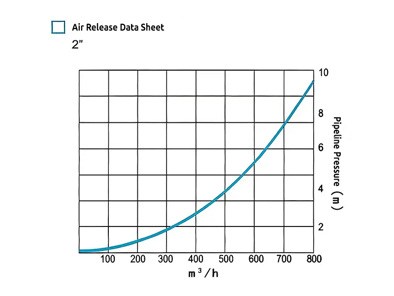
2" air release data sheet
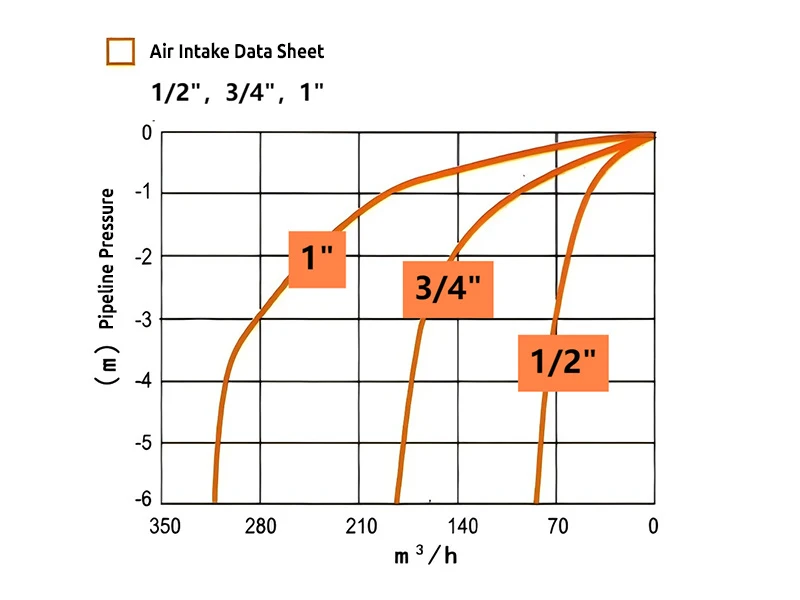
1/2", 3/4", 1" specifications air intake data sheet
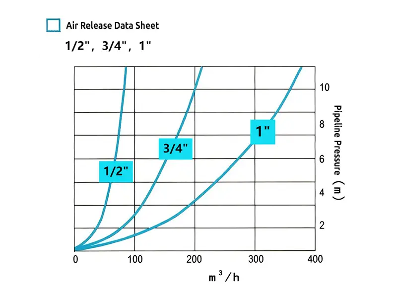
1/ 2", 3/4", 1" specifications air release data sheet