
Our electromagnetic valve is a hydraulically operated diaphragm-type valve, which controls the flow of water by opening or closing the valve through electrical signals. The electromagnetic valve has precise pressure regulation and responsive action, typically installed on branch or main pipes. It can be remotely controlled, in conjunction with sensors and timers, to achieve precise irrigation and reduce manual intervention.
Electromagnetic valves are widely used in computer-controlled irrigation systems, pressure reducing stations, systems with significant water pressure variations, energy-saving irrigation systems, pipelines that are distant or at higher elevations, pipelines with significant irrigation drop, and water distribution networks.
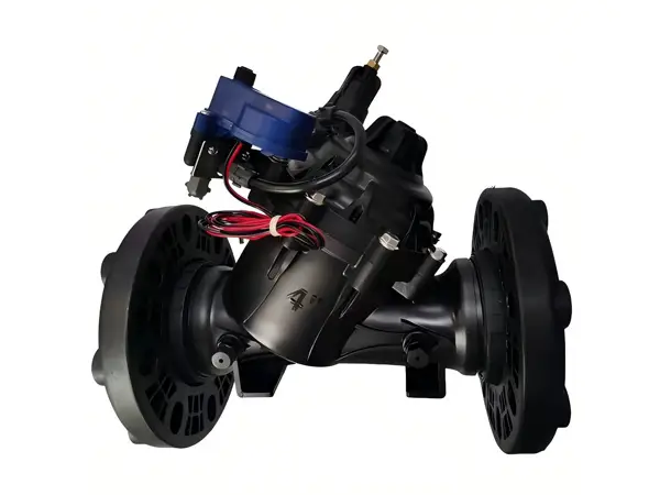

The electromagnetic valve mainly consists of a valve body (corrosion-resistant shell to protect components from erosion), a solenoid coil (receives electrical signals to control the opening and closing of the valve, can be manually opened or closed), a diaphragm (flexible diaphragm moves under pressure), and a spring (pushes the diaphragm to move).
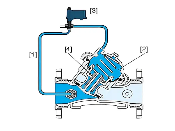
Energized state: When the electromagnetic valve receives an electrical signal, the electromagnetic coil generates a electromagnetic force, pushing the valve core to move, and the electromagnetic head opens. System pressure [1] passes through the opened electromagnetic head [3] and enters the control chamber [2], where the water pressure presses the diaphragm valve core assembly [4] down, closing the water flow channel.
De-energized state: When the electromagnetic valve is de-energized, the electromagnetic coil stops working, the electromagnetic head closes, the pressure in the control chamber [2] decreases, and the spring resets the diaphragm valve core assembly [4], opening the water flow channel.
| Color | Flow Rate L/h |
Pressure kg |
Weight g |
Material |
|---|---|---|---|---|
| Yellow | 2 | 0.5–3.5 | 3.6 | PP |
| Black | 4 | 0.5–3.5 | 3.6 | PP |
| Blue | 8 | 0.5–3.5 | 3.6 | PP |
| Model | Specifications | Connection Method | Solenoid Voltage (V) |
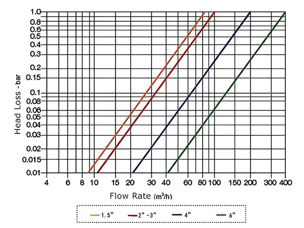
Maximum Flow Rate (m3/h) |
Operating Pressure (bar) |
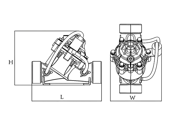
Weight (kg) |
|---|---|---|---|---|---|---|
| SV-1 | 1.5" x 1.5" | BSP / NPT | DC24V / AC24V / DC12V (pulse) | 15 | 0.35–10 | 1.56 |
| SV-2 | 2" x 2" | BSP / NPT / VIC | DC24V / AC24V / DC12V (pulse) | 25 | 0.35–10 | 1.96 |
| SV-3 | 3" x 3" | BSP / NPT / Flange / VIC | DC24V / AC24V / DC12V (pulse) | 50 | 0.35–10 | 2.04 (with flange 3.42) |
| SV-4 | 4" x 4" | Flange | DC24V / AC24V / DC12V (pulse) | 100 | 0.35–10 | 6 |
| SV-5 | 6" x 6" | Flange | DC24V / AC24V / DC12V (pulse) | 150 | 0.35–10 | 11.8 |